
Python serial interface for Neato robot vacuum cleaners. Testing on XV Signature Pro, should work on others.
Last updated Apr 26, 2026
70
Stars
14
Forks
7
Issues
0
Stars/day
Attention Score
22
Language breakdown
No language data available.
▸ Files
click to expand
README
Neato-serial
Serial interface for Neato robot vacuum cleaners. Transforms your non-connected Neato into a connected one. Tested on XV Signature Pro and Raspberry Pi, should work on others. Demo video. Uses hub-ctrl.c.Hardware required
- Raspberry Pi (2, 3 and Zero tested and confirmed working) or any other device that runs Python and has some sort of GPIO and USB connectivity.
- A mini usb cable to connect your Raspberry Pi to Neato
- A micro usb cable to power your Raspberry Pi
- A 5V step-down voltage regulator. I used one from Pololu but any should do. Make sure it can handle at least 16V as that is what Neato will be providing to power your Raspberry Pi from.
- A 5V relay (optional). I used a Grove Relay from Seeed but any 5v relay should do. The package also allows for direct USB connection, without a relay.
Setup
- Connect to your step-down voltage regulator to Neato's 16V connection. See image below to find the right connector on the Neato motherboard:
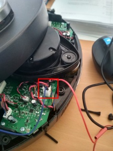
- Connect the output of the step-down voltage regulator (that should be 5V) to your Raspberry Pi's USB connector for power. Do not use the GPIO to power the Raspberry Pi directly.
- Connect a mini usb cable from the Raspberry Pi to Neato.
- If using a relay:
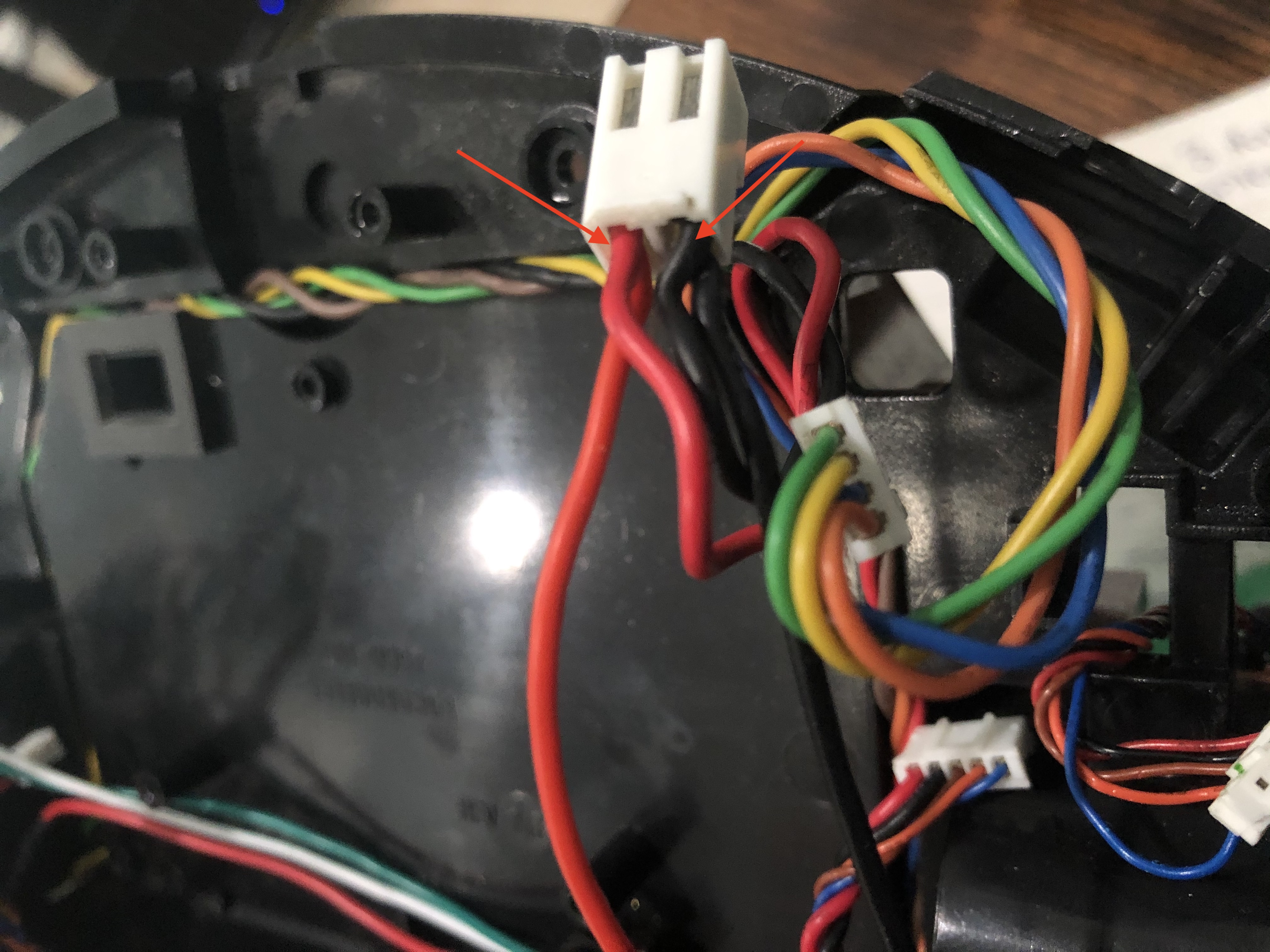 * Voltage-Regulator Wiring:
* If using the voltage-regulator mentioned above, be sure to remove the pot and solder the 5V pads on the back of voltage-regulator.
* Solder the live wire (red wire) from Neato's 16V connector (previous step) to the port labeled
* Voltage-Regulator Wiring:
* If using the voltage-regulator mentioned above, be sure to remove the pot and solder the 5V pads on the back of voltage-regulator.
* Solder the live wire (red wire) from Neato's 16V connector (previous step) to the port labeled IN+ on the voltage-regulator.
* Solder the ground wire (black wire) from Neato's 16V connector to the port labeled GND on the voltage-regulator.
* Power to the Raspberry Pi ZeroW:
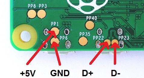
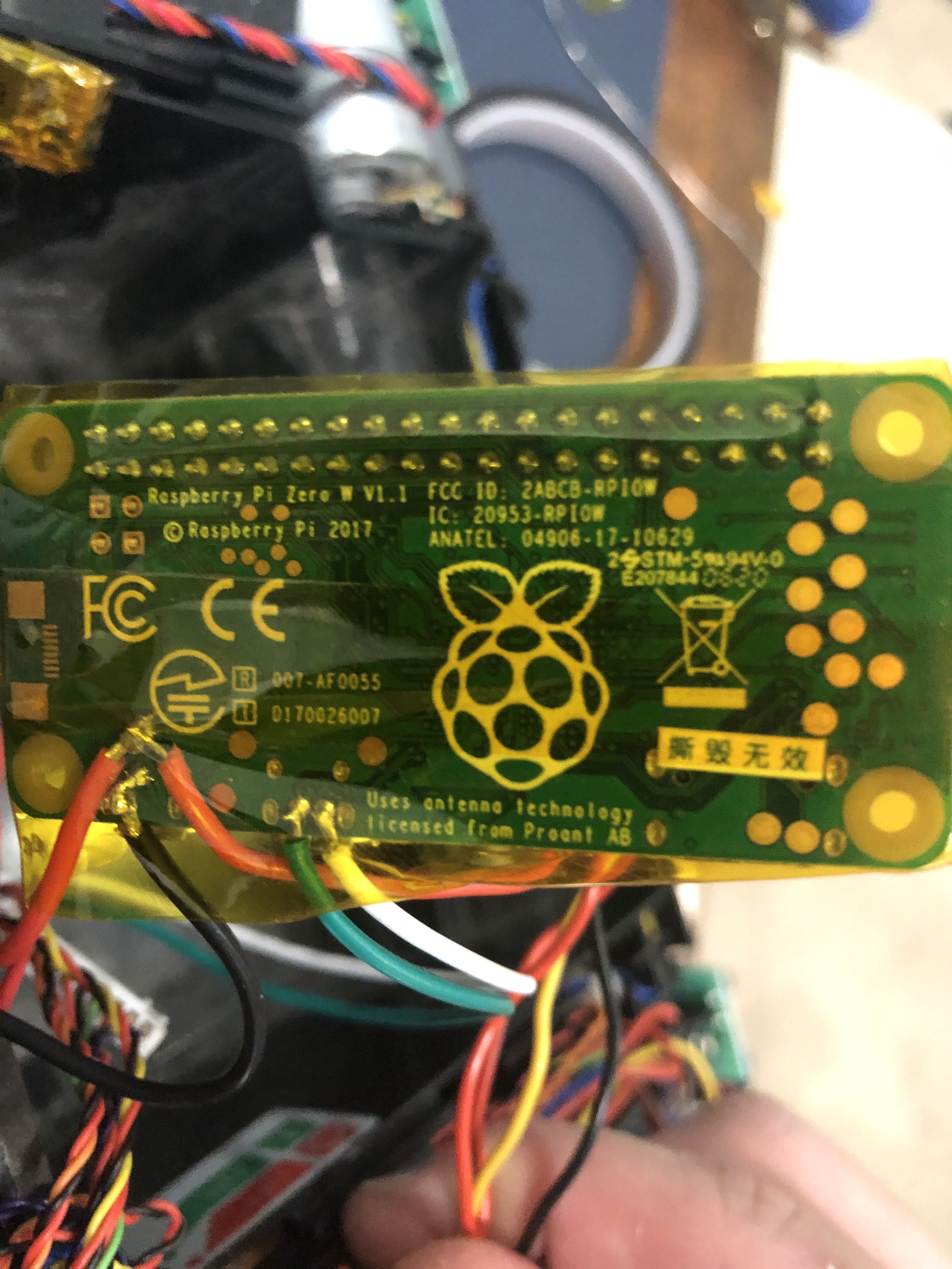
* Solder an additional wire to the port labeled GND on the voltage-regulator and the other end to the test point labeled PP6 on the underside of the Raspberry Pi ZeroW (see image below).
* Solder a wire to the port labeled VO+ on the voltage-regulator and the other end to the test point labeled PP1 on the underside of the Raspberry Pi ZeroW (see image below).
* The port labeled EN on the voltage-regulator will not be used
*  * Wiring Raspberry Pi ZeroW to Relay
* You can either use dupont connectors to connect the Pi to the relay or solder wires to the pins on the underside of the Pi.
* Connect your relay to the 5V, GND and GPIO 2 of your Raspberry Pi. If you use another GPIO make sure to reflect that in the configuration file (see
* Wiring Raspberry Pi ZeroW to Relay
* You can either use dupont connectors to connect the Pi to the relay or solder wires to the pins on the underside of the Pi.
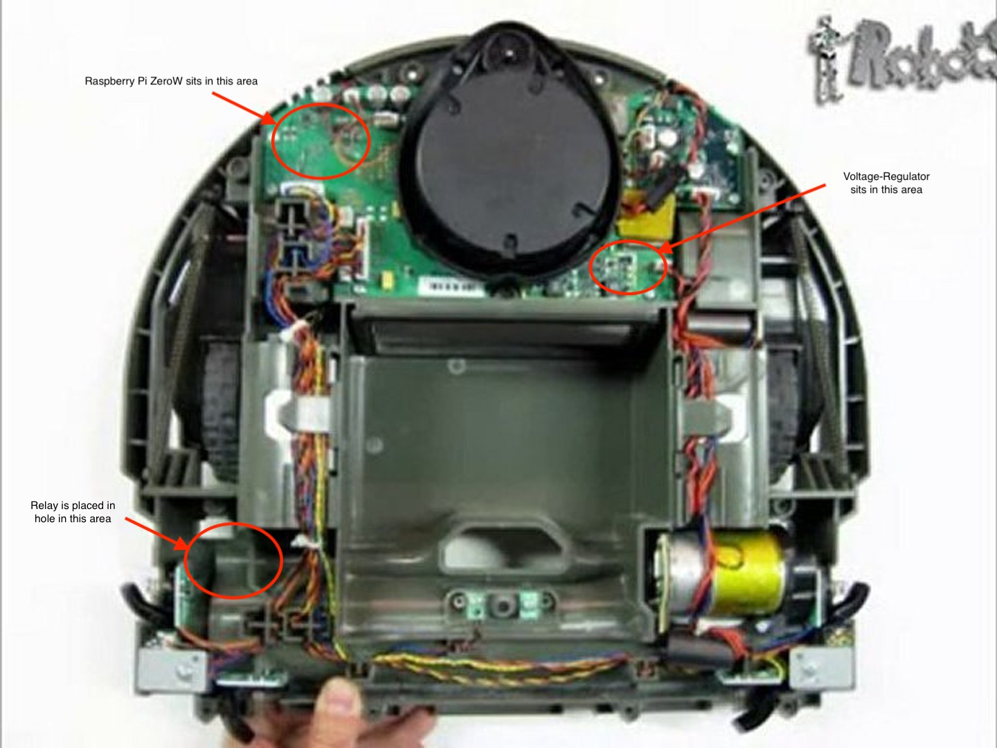
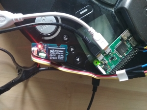
* Connect your relay to the 5V, GND and GPIO 2 of your Raspberry Pi. If you use another GPIO make sure to reflect that in the configuration file (see Configuration Section). If using a relay with screw-terminals, I recommend using ferules on the ends of the wires going into the relay screw terminals. Also, be sure to use enough wire length to allow the wires to reach from the upper-left side of the motherboard where the Pi will sit to a hole near the left wheel where the relay will sit (See image below).
* Solder another wire (preferably red) to the test point labeled PP1 on the underside of the Raspberry Pi ZeroW and place the other end into the COM port of the relay.
* We will come back to the relay in the next steps.
*  * Wiring Pi ZeroW MicroUSB port to Neato's MiniUSB port:
* Warning: When soldering to the pads on Neato's motherboard, DO NOT use high heat as these pads are weak and will pull off of the motherboard if not handled with care. Also, add some hot glue to the top of the wires/connections (once all 3 soldered connections are made) to help alleviate wire strain and prevent the pads from getting pulled up.
* If you are using JST connectors that I mentioned in the hardware section, choose either a male or female connector for the Raspberry Pi side and the opposite for Neato side ( Female connector on Pi & Male connector on Neato side or Male connector on Pi & Female connector on Neato side).
* If using JST connectors:
- Solder the
* Wiring Pi ZeroW MicroUSB port to Neato's MiniUSB port:
* Warning: When soldering to the pads on Neato's motherboard, DO NOT use high heat as these pads are weak and will pull off of the motherboard if not handled with care. Also, add some hot glue to the top of the wires/connections (once all 3 soldered connections are made) to help alleviate wire strain and prevent the pads from getting pulled up.
* If you are using JST connectors that I mentioned in the hardware section, choose either a male or female connector for the Raspberry Pi side and the opposite for Neato side ( Female connector on Pi & Male connector on Neato side or Male connector on Pi & Female connector on Neato side).
* If using JST connectors:
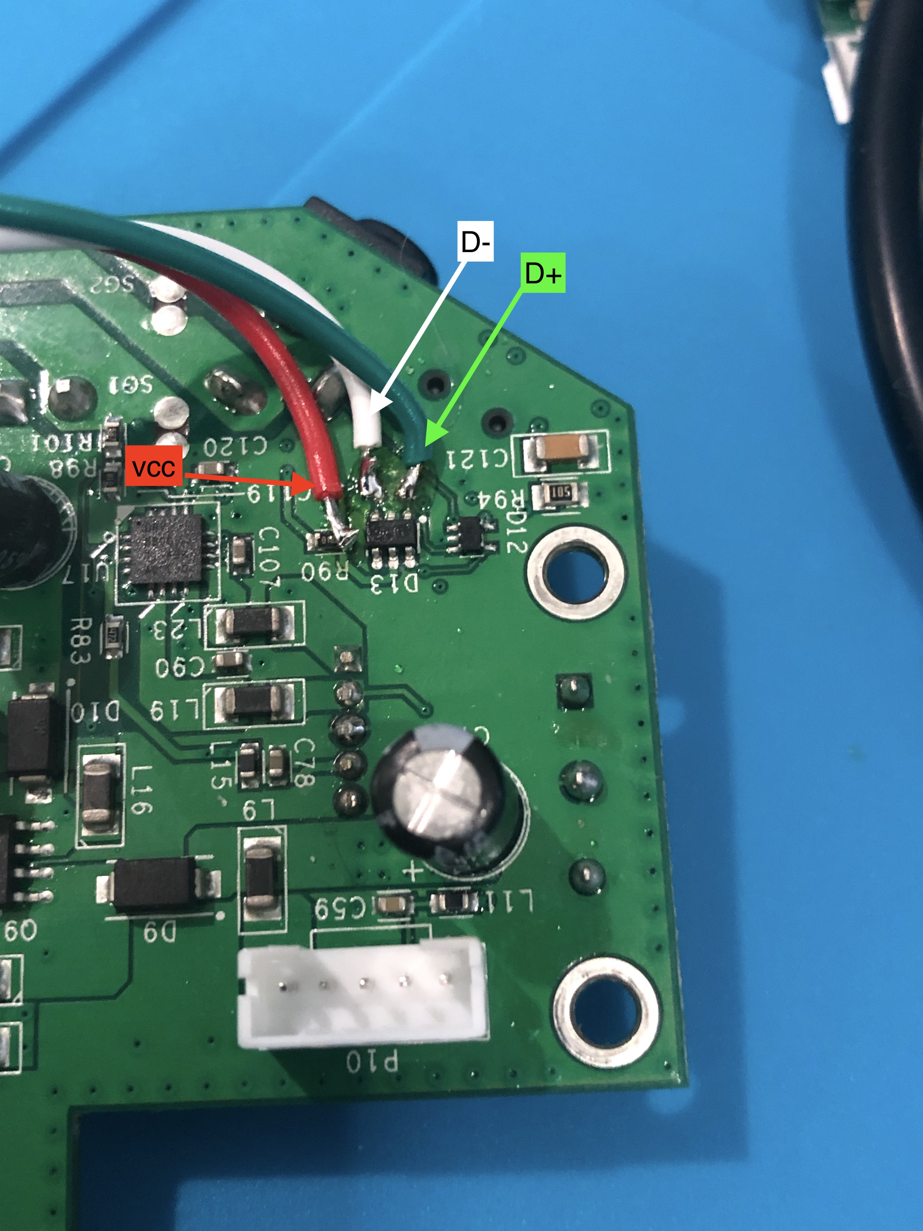
- Solder the green wire (D+) of your JST connector to the small round pad above the component labeled D13 (see image below)
- Solder the white wire (D-) of your JST connector to the small round pad above the component labeled D13 and to the left of the previously soldered green wire (see image below)
- Solder the red wire (VCC) of your JST connector to the right-side of the resistor labeled R90 (see image below)
- Be sure to add hot glue to the connections at the Neato's motherboard to alleviate wire strain and prevent pads from lifting
- With a new JST connector, solder the green wire (D+) to the test point labeled PP22 on the underside of the Raspberry Pi ZeroW (image of test points located above)
- Solder the white wire (D-) to the test point labeled PP23 on the underside of the Raspberry Pi ZeroW (image of test points located above)
- Solder the red wire (VCC) to a separate wire (be sure to add heat shrink tubing over the connection point of the two wires)- the other end of this wire goes into the relay port labeled NO
* If not using JST connectors:
- Solder a wire (preferably green) to the small round pad above the component labeled D13 (pad labeled as D+ in image below). Solder the other side of the wire to the test point labeled PP22 on the underside of the Raspberry Pi ZeroW (image of test points located above)
- Solder a wire (preferably white) to the small round pad above the component labeled D13 (pad labeled as D- in image below). Solder the other side of the wire to the test point labeled PP23 on the underside of the Raspberry Pi ZeroW (image of test points located above)
- Solder a wire (preferably red) to the right-side of the resistor labeled R90 (labeled as VCC in image below). Insert the other end of this wire into the relay port labeled NO
- Be sure to add hot glue to the connections at the Neato's motherboard to alleviate wire strain and prevent pads from lifting
*  * Wrapping up:
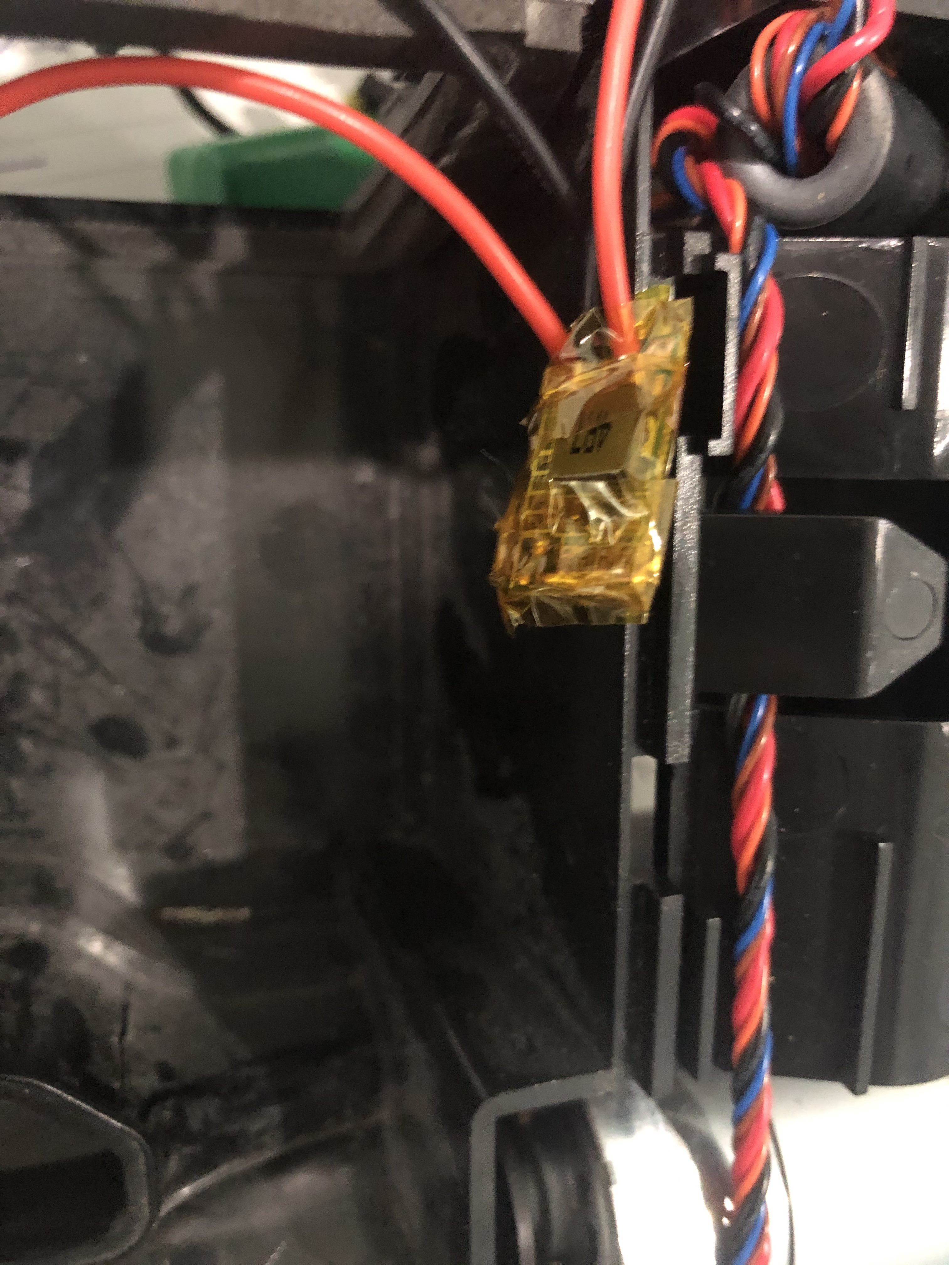
* Cover the underside of the Raspberry Pi ZeroW and the entire voltage-regulator with Kapton tape to prevent any shorts from occuring.
*
* Wrapping up:
* Cover the underside of the Raspberry Pi ZeroW and the entire voltage-regulator with Kapton tape to prevent any shorts from occuring.
* 
Installation
- install the requirements using provided
requirements.txt:pip install -r requirements.txt - install python-systemd by running
sudo apt-get install python3-systemd - create
config.yamlby copying theconfig.yaml.exampleprovided and setting the correct values. See below for settings.
Configuration
Configuration values:- serial:
/dev/ttyACM0,/dev/ttyACM1
- timeout_seconds: timeout in seconds to use for the serial connection.
Example value: 0.1
- usbswitchmode: specifies if you connected Neato directly through a USB cable or through a relay.
Options: direct or relay:
- direct. Tested on Raspberry Pi 2 and 3. Does not work on Raspberry Pi zero since usb port cannot be turned off - use relay instead. Connect your Pi and Neato directly using an USB cable:
 This option does require elevated permissions (
sudo) for the script since it needs to disable the usb port and (depending on config) reboot the Pi.
- relay. Switches the USB connection using a relay. Tested to work on Raspberry Pi zero and others. This is the only method that works on Raspberry Pi zero. Be sure to also specify the GPIO the relay is connected to with relaygpio. Connect a 5V relay to your Raspberry Pi. Cut your USB wire and re-connect all the cables except the red one. Wire the red cable through the relay (one side into Common and the other into NO if you have three connectors on your relay). I used a Grove Relay from Seeed but any relay should do.
 Example value:
 direct
- relaygpio: specifies the GPIO the relay is connected to when using usbswitch_mode: relay.
- rebootafterusb_switch: specifies to reboot after usb has been switched off. Usefull if your Raspberry Pi does not reconnect after the USB has been disabled and enabled. Use with caution and only when running this script as a service.
Example value: True
- mqtt:
1883
- discovery_topic: auto-discovery topic. Example value: hass
Uncomment this and add your Home Assistant auto-discovery topic if you intend to have Home Assistant add the vacuum automatically. If you intend to manually (legacy method) set the vacuum up in Home Assistant leave this commented out - See sample configuration under Usage section if using legacy method.
- command_topic: MQTT topic for receiving commands.
Example value: vacuum/command
- state_topic: MQTT topic for publishing state.
Example value: vacuum/state
- publishwaitseconds: Delay in seconds before updating state again.
Example value: 5
Usage
Two modes are available (start either usingpython3 xx.py).
- interactive console mode:
neatoserial.py - mqtt mode:
neatoserialmqtt.py, for integration in MQTT scenario. Built for integration with Home Assistant via MQTT Vacuum component but should be usable elsewhere as well. Run this script as a service using systemctl to get the integration working (see providedneatoserialmqtt.servicefile). - Sample configuration for Home Assistant:
discovery-topic in the configuration file, you do not need to do this.
vacuum:
  - platform: mqtt
    name: "Neato"
    supported_features:
      - turn_on
      - turn_off
      - send_command
      - battery
      - status
      - locate
    command_topic: "vacuum/command"
    batteryleveltopic: "vacuum/state"
    batteryleveltemplate: "{{valuejson.batterylevel}}"
    charging_topic: "vacuum/state"
    chargingtemplate: "{{valuejson.charging}}"
    cleaning_topic: "vacuum/state"
    cleaningtemplate: "{{valuejson.cleaning}}"
    docked_topic: "vacuum/state"
    dockedtemplate: "{{valuejson.docked}}"
    sendcommandtopic: "vacuum/command"
    payloadturnon: "Clean"
    payloadturnoff: "Clean Stop"
    payload_locate: "PlaySound 19"
    fanspeedtopic: "vacuum/state"
    fanspeedtemplate: "{{valuejson.fanspeed}}"
Commands
See the Neato programmers manual for available commands. It seems that some commands are not listed in the manual:- Clean Stop stops the vacuum. - Clean Spot tells the vacuum to do a spot clean


