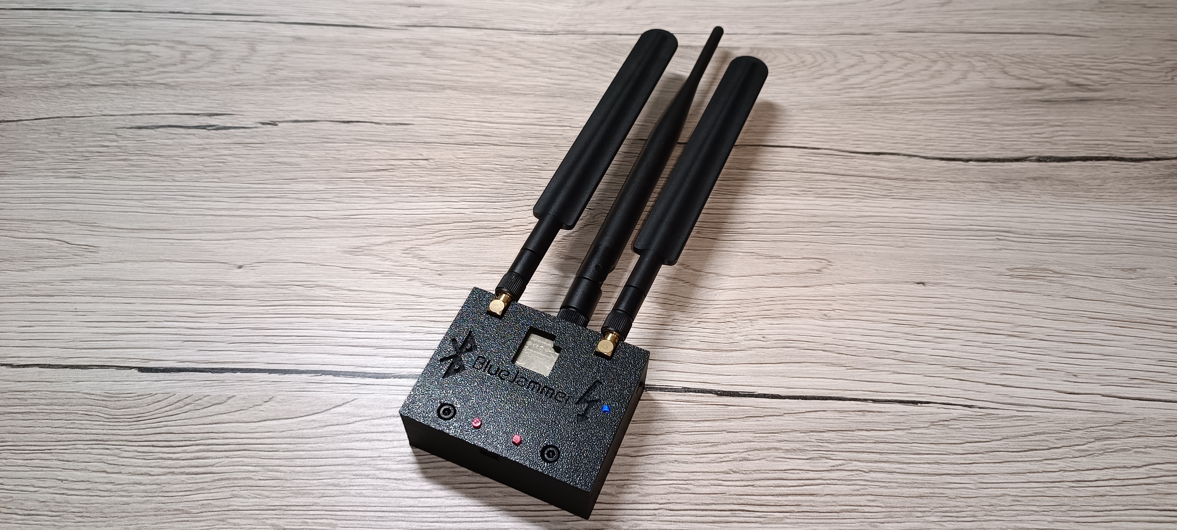
The ESP32-BlueJammer (Bluetooth jammer, BLE jammer, WiFi jammer, RC jammer) disrupts 2.4GHz communications. Using an ESP32 and nRF24 modules, it generates noise and unnecessary packets, causing interference between the devices communicating, making them unable to work as intended. Ideal for controlled disruption and security testing.
ESP32-BlueJammer - by @emensta
Jamming is ILLEGAL! Educational purposes only!
BlueJammer-V2, BW16-BlueJammer & ZeroWave for Flipper Zero released!


Make your own | Schematics | Hardware layout | PCB's | Demos | Channels | Flashing | 3D case | About | Support me | Website
ESP32-BlueJammer
The ESP32-BlueJammer (Bluetooth jammer, BLE jammer, WiFi jammer, RC jammer) disrupts various devices using an ESP32 and nRF24 modules, causing plenty of noise and sending unnecessary packets (DoS). It interrupts: The whole 2.4GHz broadband! Everything that works on 2.4GHz is being interfered, like: audio in speakers being transmitted over bluetooth, microphones on 2.4GHz, smartphone connections, WiFi, RC Drones (etc.), IoT devices, smart gadgets, wireless keyboard & mouse, just anything on 2.4GHz!Ideal for controlled disruption and security testing. Based on 2.4GHz communication.
It has a big range (over 30Meters+ - may vary on your antenna and hardware setup!) on newest Bluetooth versions with casual 2.4GHz antennas, you can easily increase this as well by taking some simple "bigger" router antennas. An amplifier (2.4GHz) may be a good option too!
Remember that jamming is illegal and should not be used with malicious intent!
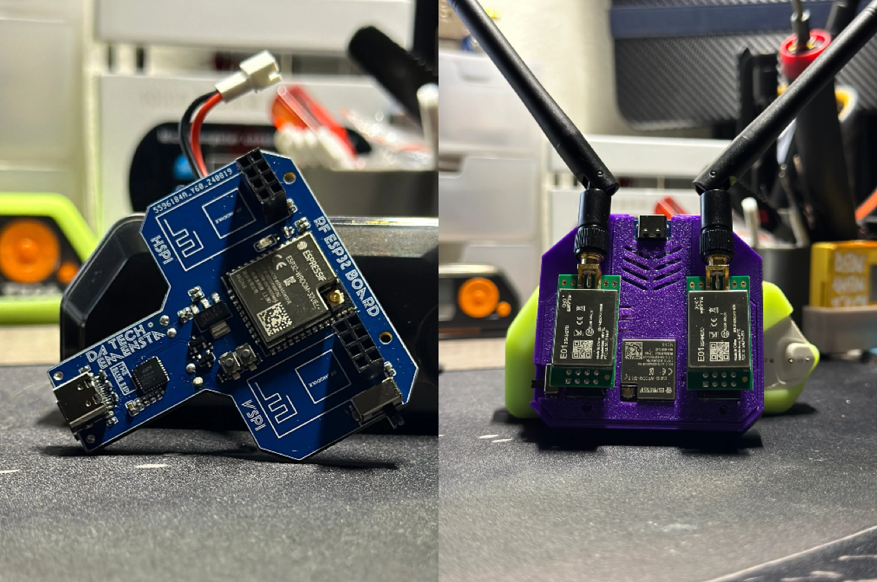
PCB's with ESP32 and RF-module capability
ESP32-RF DIY-PCB: This PCB can fit an ESP32-wroom-32U/E DevKitC and 2 nRF-modules, along with an 0.96" I2C OLED, LEDs and switches. Remember: It is not intended for illegal use! For this one, all you need is listed below:Required:
- ESP32 Dev Module (Recommended: ESP32-32U CP2102, any ESP32 should work as long as it has the needed pins, 38P required!)
- nRF24L01+PA+LNA (2x)
- 10-100uF Capacitor (2x) (any voltage above 5V)
- 0.96" OLED Display I2C
- Slide Switch (2x)
- LEDs: 3mm LED box
- Resistor kit
- R1 = 1kOhm
- R2, R3, R5, R7 = 47kOhm
- R4, R6 = 100kOhm
- TP4056 Charging Module (Micro-USB/Type-C)
- JST PH 2.0 Connector
- 3.7V Li-Ion Battery
- 3rd Antenna: IPEX to SMA-F pigtail**
PRE-SOLDERED: "The Blue ESP" This is an ESP32 with RF-module breakouts (nRF24/CC1101 etc.) for experimenting. Remember: It is not intended for illegal use, neither for my project!
Required:
- nRF24L01+PA+LNA (2x)
 Shop
Shop
Video tutorials and demonstrations
Full DIY assembling video tutorialFull DIY assembling video tutorial (if the TikTok is not available for you)
Demonstration (if the TikTok is not available for you)
Flashing process (if the TikTok is not available for you)
ESP32-BlueJammer tutorial by @ElMackflay 
Operation Channels
- Bluetooth = 79CH
- BLE = 40CH
- WiFi = 14CH
- RC drones, etc. = 1-125CH
How to use?
To disrupt various channels on the 2.4GHz band, do the following to enable your ESP32-BlueJammer:- Every mode starts right away after powering on the device! There is no additional button to start the attack!
- It simply jams right away once powered!
Combo-Channel-Select_BT-BLE-WiFi-RC firmware:
- use the "Boot" button on the ESP32 to switch between the channel modes on the Combo-Firmware!
- the OLED will display your current operation channel
- the status LED lets you know about the current state you're in:
- the serial output of your ESP32-BlueJammer will output the following lines when switching mode:
all other firmware:
- the firmware you choose indicates the operation channel by its name, this means:
BluetoothLowEnergy40CH - jams Bluetooth Low Energy Frequency Range: 2.400 GHz to 2.4835 GHz
Bluetooth-BluetoothLowEnergy40-80CH - jams classic Bluetooth & Bluetooth Low Energy Frequency Range: 2.402 GHz to 2.480 GHz & 2.400 GHz to 2.4835 GHz
Bluetooth-WiFi14-80CH - jams classic Bluetooth & WiFi Frequency Range: 2.402 GHz to 2.480 GHz & 2.400 GHz to 2.4835 GHz
WiFi14CH - jams WiFi Frequency Range: 2.400 GHz to 2.4835 GHz
2.4GHzRemoteControl(Drones etc.)1-125CH - jams RC (Drones etc.) Frequency Range: 2.400 GHz to 2.525 GHz
Hardware - Make your own ESP32-BlueJammer
(Aliexpress affiliate links to support me-linked to the item names)Required:
- ESP32 Dev Module (Recommended: ESP32-32U CP2102, any ESP32 should work as long as it has the needed pins)
- nRF24L01+PA+LNA (2x)
- 10-100uF Capacitor (2x) (any voltage above 5V)
- Prototype PCB (at least 7x9 cm, but you will need to cut it down to fit the 3D-printed case, which fits a size of 7x5,5cm!)
Additional:
If you're looking to add a battery:
- 3.7V Li-Ion Battery
- JST PH 2.0 Connector
- TP4056 Charging Module (Micro-USB/Type-C)
- Mini Slide Switch
To screw the 3D printed case together you must have:
- M3x16 Screws (2x)
- M3 Nuts (2x)
Antennas
A frequently asked question is whether the antennas are needed and what the third antenna is for, here is the answer: Yes, you need at least both antennas for the nRF24's! Why? To have it working on a decent range! The average range with standard known chinese 2.4GHz antennas is about 20-30meters. Upgrading those antennas will help a lot with getting more range!2 antennas are for the HSPI and VSPI nRF24 modules!
The 3rd antenna is plugged to the ESP32 chip itself, whether via IPEX or soldered onto its own antenna, if your ESP32 does not provide any option to add that one, it obviously won't be possible! What is the 3rd antenna used for? The third antenna connected to the ESP32 chip itself helps with reliable long-range interference. It ensures a better intermediate signal and stability when jamming! (The third antenna is your own decision and therefore optional!)
Flashing the firmware
via webflasher (Easy)
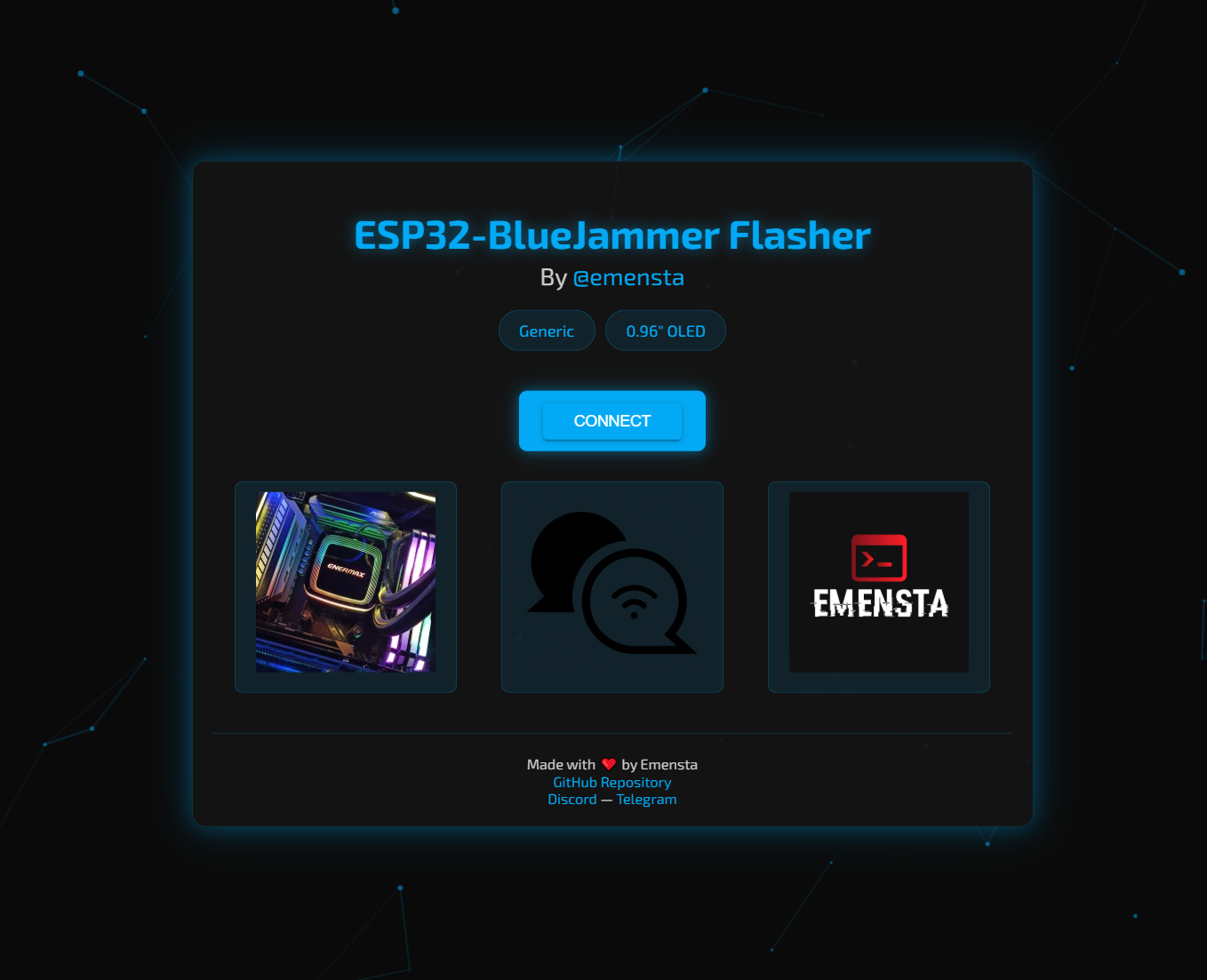 I've created a webflasher to make it super easy for you to flash your ESP32 chip with the ESP32-BlueJammer firmware of your choice!
- Visit ESP32-BlueJammerFlasher
- First, choose the firmware type, "Generic" or "0.96" OLED"
- choose the firmware you want to flash
- Connect your ESP32 via a data USB cable
- Flash the firmware of your choice :D
Flashing ESP32 via binary files (Advanced)
- Download the .bin files available on this repository
- Use any flasher of your choice
- Flash it :D
ESP32-nRF24L01+ pinout + battery mod
Here are both pinouts for HSPI and VSPI. You need both nRF24L01 modules connected in order to achieve full capability of the device. nRF24L01+ pinoutHSPI
| 1st nRF24L01 module Pin | HSPI Pin (ESP32) | 10uf capacitor | |---------------|------------------|--------------------| | VCC | 3.3V | (+) capacitor | | GND | GND | (-) capacitor | | CE | GPIO 16 | | CSN | GPIO 15 | | SCK | GPIO 14 | | MOSI | GPIO 13 | | MISO | GPIO 12 | | IRQ | |VSPI
| 2nd nRF24L01 module Pin | VSPI Pin (ESP32) | 10uf capacitor | |---------------|------------------|--------------------| | VCC | 3.3V | (+) capacitor | | GND | GND | (-) capacitor | | CE | GPIO 22 | | CSN | GPIO 21 | | SCK | GPIO 18 | | MOSI | GPIO 23 | | MISO | GPIO 19 | | IRQ | |Status LED
| ESP32 | 4.7k Ohm Resistor | 3mm Status LED (blue)| |-------|-------------------|----------------------| | GND | | (-) LED | | | Resistor | (+) LED | |GPIO27 | Resistor | |OLED Display I2C (additional - make sure to use the correct firmware!)
| 0.96" OLED Display I2C | ESP32 | |------------------------|-------| | GND | GND | | VCC | 3.3V | | SCL |GPIO 5 | | SDA |GPIO 4 |Battery modification (additional)
| 3.7V Li-Ion battery | JST-PH2 connector | TP4056 Charging Module | Mini Slide Switch | ESP32 | |---------------------|----------------------|------------------------|-------------------|-------| | (+) Battery | (+) JST-PH2 | Bat + | | | | (-) Battery | (-) JST-PH2 | Bat - | | | | | | OUT + | Switch in | | | | | OUT - | | GND | | | | | Switch out | 3V3 |PCB
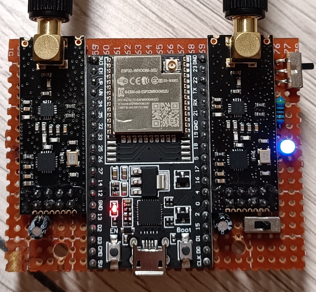
That's how the components are placed (PCB size=7cm x 5.5cm - Larger sizes will NOT fit in the case!)
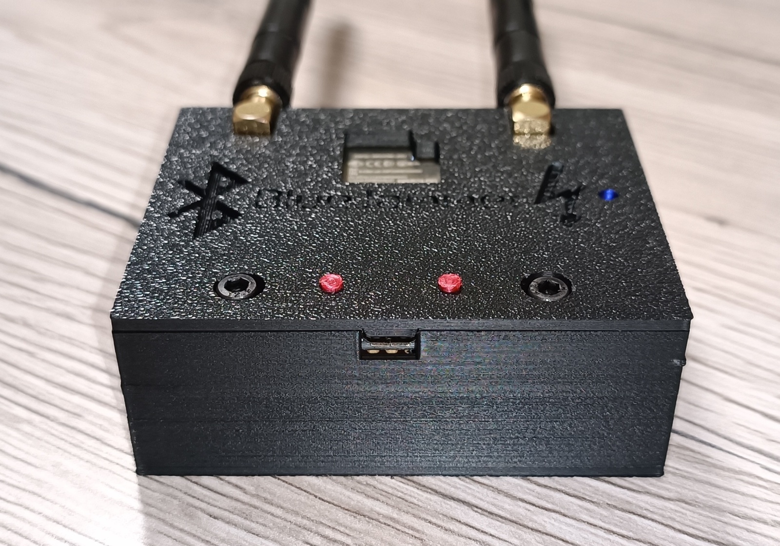
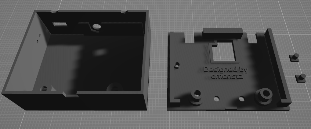
3D printed case
The 3D printed case fits ONLY a PCB size of 7cm x 5.5cm and you'll need to drill out 2 holes according for the M3 screws to fit through the PCB!
Access to the ESP32 micro-USB port, as well as to both EN & Boot buttons
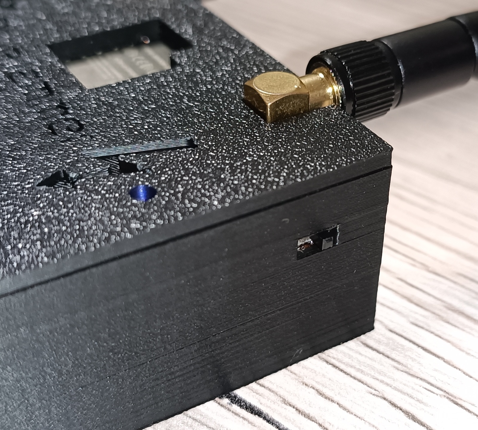
TP4056 charging port access with charging state indicator holes (red=charging - blue=fully charged)

On/off switch with blue indicator LED
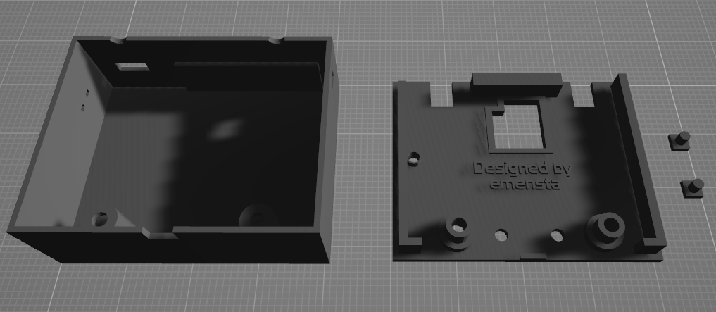
V3-Case 3D model view [download .stl]
Here's a look at the V3 2 antenna version itself
V4-Case 3D model view [download .stl]
Here's a look at the V4 3 antenna version itself
About the ESP32-BlueJammer and my source code
- Is my ESP32-BlueJammer really working?
- Why my ESP32-BlueJammer code is NOT open source
Despite some claims that I might have copied someone else's work, it's important to clarify that extracting source code from a compiled file (.hex, .bin, etc.) is practically impossible. If I had used someone else's work, I wouldn't have been able to create custom console banners, develop multiple firmware versions, or build a web flasher. My code is entirely written from scratch. There is nothing taken from other available codes, sources, codebases or resources as a foundation, if any even exist. My code remains closed source for now, to protect the significant effort and innovation I've invested in this project.
This isn't my last project. I'm looking forward to implementing the ESP32-BlueJammer in further ongoing projects, so for now, I'd like the code to remain closed source. Maybe someday I'll make it open source! -no one knows. ;D
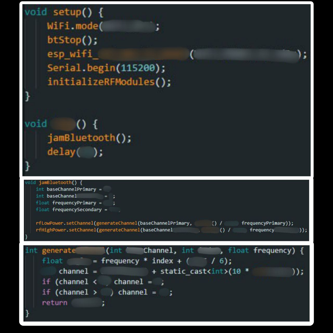
Source code snippets by @emensta
- Here are three snippets of my source code for you to compare with other available sources. This way, you can see that it was written from scratch: